
A 100-metre wind turbine blade cannot travel down a European country road. It cannot pass under a nineteenth-century stone bridge, squeeze between two barns on a hairpin turn, or negotiate a roundabout designed for delivery vans. This single logistical reality is the pivot on which any meaningful wind turbine design comparison turns. Offshore turbines have grown from 3 MW to 15 MW in two decades. Onshore machines have grown substantially more slowly, constrained by transport logistics. A turbine engineered for the North Sea is not simply a larger version of one designed for Schleswig-Holstein. They share a basic layout-three blades, upwind rotor, horizontal axis. But almost every detailed design decision diverges once transport constraints enter the equation.
Now add a third category that barely features in mainstream turbine design discussions: the small, distributed machine built for a farm, a remote telecom tower, or an island microgrid. That turbine operates at low hub heights in turbulent air. It must be serviceable by a local electrician. It competes against solar photovoltaic systems that have seen relentless cost declines over the past decade. The three groups share the same underlying physics-the Betz limit applies equally to all. But the engineering that emerges from each application is so different that treating “wind turbine” as a single category obscures more than it reveals.
The Common Ancestor: Denmark’s 1970s Design Legacy
The modern wind industry traces its engineering roots to a specific time and place: Denmark in the 1970s and early 1980s. Small manufacturers, often agricultural machinery companies, began building three-bladed, upwind, horizontal-axis turbines with asynchronous generators. This configuration-later called the Danish Concept-established the template that still dominates global turbine design. Why it emerged in that form deserves a closer look, because the constraints those early designers faced continue to echo through the industry.
The early Danish machines were modest. A 55 kW turbine with a 15-metre rotor diameter was considered substantial. The design brief was determined by practicalities that might surprise anyone accustomed to today’s industrially serviced machines. The entire nacelle had to be serviceable from inside using basic tools. The tower had to be tiltable-lowered to the ground by a farmer’s own tractor-so that blade repairs could be carried out without an expensive crane. The machine had to survive North Sea storm gusts without active pitch control, because the control systems of the era were too slow to respond reliably.
The result was a robust, mechanically simple machine that could be built in a barn and maintained by a farmer with no specialist heavy-lift equipment. Its virtues were the direct product of those constraints-a machine simple enough to understand and reliable enough to repair with basic tools. That accessibility, more than any single innovation, was what allowed wind power to take root in rural Denmark. It was also the seed from which two very different design families would grow.
From that common origin, the development path forked. Onshore turbines grew taller and more powerful, but always within the envelope dictated by road transport. Offshore turbines escaped that envelope entirely. The divergence widened further once floating platforms entered the design conversation. The two branches now share little beyond the basic Danish Concept silhouette.
The Physics That Governs Every Decision
Every wind turbine designer begins with the same equation. Power extracted from the wind scales with the swept area of the rotor and the cube of wind speed. Double the rotor diameter, quadruple the swept area. Double the wind speed, increase available power eightfold.
This is why turbines grew. A larger rotor captures more wind. A taller tower reaches faster, smoother air. A 15 MW offshore machine with a 236-metre rotor diameter can generate more electricity in a single day than a 1980s 55 kW turbine could generate in a year.
The physics also sets a hard ceiling. The Betz limit-derived by Albert Betz in 1919-states that no turbine can extract more than 59.3 percent of the kinetic energy in the wind passing through its rotor disc. Modern utility-scale machines achieve 45 to 50 percent aerodynamic efficiency. The gap reflects an economic trade-off. Chasing the final few percentage points requires blade geometries that are expensive to manufacture, difficult to transport, and sensitive to surface roughness from insect accumulation or leading-edge erosion. The industry learned early that spending capital on a larger rotor-capturing more wind at slightly lower efficiency-delivers better energy economics than perfect aerodynamics.
That insight explains more about turbine scaling than any other engineering consideration. Rotor diameter matters more than the aerodynamic efficiency coefficient. The same principle applies in solar photovoltaics, where module area drives energy output far more than incremental cell efficiency gains (How Solar PV Systems Convert Sunlight into Grid-Ready Electricity). But where a solar farm can expand by adding more modular panels, a wind project’s economics are tied to the size of the individual machine. That size is determined by what can physically reach the site.
Onshore Design: Logistics as the Dominant Constraint
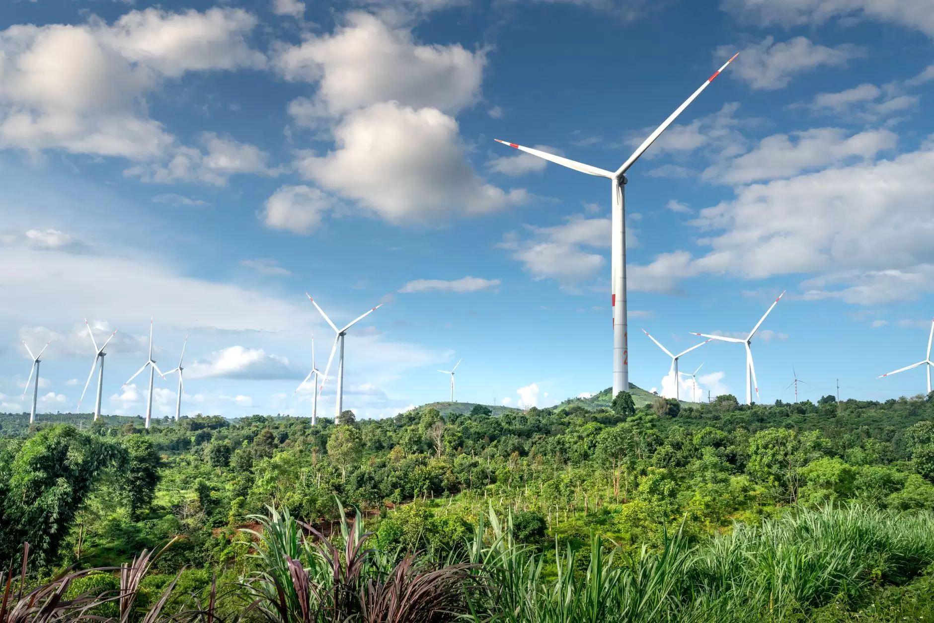
Onshore turbine design is an exercise in transport logistics. Every component-blade, tower section, nacelle, generator-must travel by road from factory to site. This imposes hard constraints that no aerodynamic optimisation can override. Blade length is limited by bridge clearances, tunnel heights, road widths, and corner radii. A 70-metre blade, standard for a 5 to 6 MW onshore machine, requires route surveys, police escorts, and sometimes temporary road modifications. Tower diameter is constrained by underpass heights. Nacelle weight is limited by the crane capacity that can be economically mobilised to a rural construction site.
These constraints have shaped onshore architecture in specific ways. Blades increasingly incorporate carbon fibre reinforcement to achieve longer lengths without proportional weight increases. Towers are often modular steel sections bolted together on site. Concrete-steel hybrid towers are becoming common for hub heights above 120 metres.
Generator technology has followed a parallel path. Many onshore turbines now adopt permanent-magnet direct-drive configurations, eliminating the gearbox entirely. Removing that component reduces nacelle weight and removes a major maintenance burden, but it shifts the trade-off to a reliance on rare-earth magnets. Those materials introduce supply chain exposure and price volatility, so the design choice is not purely technical-it also reflects procurement strategy and long-term service planning.
The operational context matters equally. Onshore turbines are designed for component replacement over a 20- to 25-year service life. Gearboxes, generators, main bearings, and blades are all replaceable. The economic logic assumes a technician can drive to the site, mobilise a moderate-capacity crane, and swap a failed component within weeks. This dictate governs bearing selection, lubrication system design, and structural connections that are bolted rather than welded.
Onshore turbines also face constraints that offshore machines largely avoid. Noise regulations, shadow flicker limits, aviation lighting requirements, and visual amenity considerations all influence siting decisions. These do not change the aerodynamic design directly, but they affect tip-speed ratio selection and operational curtailment strategies that reduce annual energy production. A turbine that must slow its rotation during certain wind directions to manage noise produces less electricity. That lost production gets priced into project economics.
Offshore Design: When Transport Constraints Disappear
Offshore turbine design starts from a fundamentally different premise. Transport constraints largely vanish. The turbine is assembled at a port facility, loaded onto an installation vessel, and erected at sea using cranes that have no road-weight limits. This single freedom has allowed offshore turbines to grow at a rate that onshore machines cannot match. In 2010, a 3.6 MW offshore turbine was considered large. By 2024, 15 MW machines with 236-metre rotors were entering commercial operation. Designs of 18 to 20 MW were in advanced engineering. The growth trajectory has been steeper than that of any other electricity generation technology, driven directly by the absence of the transport constraint that defines onshore design.
But offshore design introduces its own constraints, and they are unforgiving in a different way. Corrosion from salt spray affects every exposed surface. Wave loading on the foundation creates fatigue cycles that onshore turbines never experience. Lightning protection must account for the absence of natural grounding paths. Access for maintenance depends on weather windows that can close for weeks during winter storms.
The most consequential design shift is the approach to reliability. An offshore turbine’s major components-gearbox, generator, main bearing-are designed for substantially higher reliability than onshore equivalents, reflecting the extreme cost of offshore repair at sea. The crane vessel mobilisation costs for a major component swap can exceed several million euros. Weather risk can delay the operation by months. In some cases, the economics of repairing a mid-life offshore turbine are so unfavourable that operators choose to run the machine at reduced capacity rather than attempt a major repair.
This changes material selection, bearing sizing, and lubrication system design. Offshore turbines use larger bearings with higher safety factors. They rely on more sophisticated condition monitoring-vibration sensors, oil particle counters, SCADA anomaly detection. Increasingly they adopt medium-speed geared drivetrains with permanent-magnet generators. That configuration balances nacelle weight, partial-load efficiency, and reliability in ways that differ from both high-speed geared onshore and low-speed direct-drive offshore alternatives.
Foundation design adds another layer of complexity. In shallow water, monopile foundations-single steel tubes driven into the seabed-dominate. In deeper water, jacket structures or floating platforms become necessary. The turbine itself must be designed to accommodate the dynamic response of the foundation. A floating turbine moves with waves, introducing additional degrees of freedom that affect blade aerodynamics, drivetrain loading, and control system response. Designing for this environment requires integrated modelling of wind, wave, and structural dynamics that goes far beyond what onshore design demands.
Distributed Wind: A Different Problem Entirely
Distributed wind-turbines installed close to the point of consumption, typically smaller than utility-scale machines-operates in a design space that shares almost nothing with utility-scale machines. The constraints are different, and so are the engineering solutions.
The fundamental challenge is wind resource quality. Small turbines operate at lower hub heights, typically 10 to 30 metres. Wind speeds there are lower. Turbulence from buildings, trees, and terrain is far more intense. A distributed turbine rarely sees the smooth airflow that a 150-metre hub-height onshore machine enjoys. Turbulence reduces energy capture and accelerates fatigue. Turbulence intensity in a typical built-environment location can be two to three times higher than at a well-sited utility-scale wind farm.
This changes rotor design. Distributed turbines often use higher solidity rotors-more blade area relative to swept area-to improve starting torque in gusty, low-speed conditions. Some use furling mechanisms or passive blade pitching to protect against overspeed in high winds, avoiding the cost and complexity of active pitch control. The generators are frequently permanent-magnet machines producing variable-frequency AC. That power gets rectified to DC and then inverted to grid-compatible AC. The power electronics path adds cost per kilowatt, but it also provides the flexibility needed for turbulent wind conditions.
The economic equation is entirely different as well. Utility-scale wind benefits from economies of scale that distributed wind cannot access. A 5 MW onshore turbine might cost $1,200 to $1,500 per kilowatt installed. A 10 kW distributed turbine can run $5,000 to $8,000 per kilowatt. The gap is structural, not a manufacturing shortfall. Small turbines still need a tower, foundation, control system, inverter, and grid connection, and those fixed costs do not scale down linearly.
Cheap solar photovoltaics have narrowed the remaining niche further. With utility-scale solar now cost-competitive with fossil generation in many regions, the economic case for distributed wind depends on site-specific conditions where solar is not an option or where the turbine can plug into existing infrastructure. Distributed wind therefore makes economic sense only in specific niches.
Those niches include locations where grid connection costs are prohibitive, where diesel generation is the alternative, or where the turbine can be integrated into an existing electrical installation without extensive new infrastructure. Farms, remote telecommunications towers, island communities, and industrial facilities with consistent on-site wind resources are the natural applications. The design reflects this: simplicity, serviceability by local technicians, and tolerance for imperfect wind conditions matter more than maximum aerodynamic efficiency.
From Turbine to Grid: Integration Challenges by Type
The design choices described above are not merely mechanical engineering decisions. They directly affect how wind power interacts with electricity grids-and how grids must adapt to accommodate it.
Onshore turbines, connected to transmission or distribution networks across diverse geographic areas, produce generation profiles shaped by local meteorology. All onshore turbines share a common characteristic: output varies with weather, and that variability must be managed by the system operator through forecasting, dispatchable backup, and interconnection with neighbouring regions. Modern onshore turbines contribute to grid stability through power electronic converters that provide reactive power support, fault ride-through capability, and-in some configurations-synthetic inertia. The shift from fixed-speed induction generators to full-converter or doubly-fed induction generator architectures has transformed turbines from passive energy sources into active grid participants.
Offshore turbines add another dimension. Wind farms are large, concentrated, and connected via high-voltage submarine cables. Cable capacitance creates reactive power management issues, and distance from shore complicates voltage control. If an offshore farm trips-from a grid fault or internal protection event-the sudden loss can be large enough to affect system frequency. A project like the 1,200 MW Hornsea 1 requires specific contingency planning by the system operator.
The generation profile also differs. Offshore capacity factors often sit in the 45 to 55 percent range, compared with 25 to 35 percent onshore. Output is not perfectly correlated with demand. Northern European offshore wind produces more energy in winter, aligning with heating-driven electricity demand. US East Coast offshore wind also peaks in winter. Still, the daily profile requires complementary resources-storage, flexible demand, interconnection-to match supply with consumption.
Distributed wind operates at the opposite end of the integration spectrum. A 10 kW turbine connected behind a customer meter affects the local distribution network differently than a 500 MW offshore farm connected to the transmission system. The challenges are voltage regulation on low-voltage feeders, reverse power flow during periods of high generation and low on-site demand, and power quality issues related to the turbine’s inverter. These are distribution-level problems, managed by different entities using different tools than the transmission-level challenges of utility-scale wind.
Wind’s variability pattern differs fundamentally from solar’s diurnal cycle. A high-pressure system can deliver steady wind for days, while solar output collapses predictably every evening. Grid operators therefore hold different types of reserves for each technology. Wind-dominant systems lean more on longer-term storage and interconnection; solar-dominant systems depend on short-duration batteries and fast-ramping generation. This distinction shapes the complementary flexibility each resource requires and helps explain why regions with strong winter wind resources invest less in intraday storage than sun-belt regions.
None of these integration challenges is insurmountable, but the solutions differ between turbine categories. Assuming that one approach works for all wind generation is a recurring mistake in electricity policy discussions. The turbine’s design and siting determine its grid interaction; the grid’s architecture determines what that interaction costs.
Where Design Choices Lead Next
The divergence between onshore, offshore, and distributed turbine design is widening.
Onshore turbines are approaching a plateau in rotor diameter. The limit is logistics, not aerodynamics. Innovation is shifting toward higher hub heights, modular tower construction, and control strategies that extract more energy from sites with complex terrain and wind shear. The next generation of onshore machines will likely look similar in rotor diameter to current models, but they will be installed on taller towers in locations previously considered uneconomic.
Offshore turbines continue to scale upward. 20 MW designs are now in engineering development. The limiting factor is shifting from turbine technology to installation vessel capacity and port infrastructure. Whether 25 MW turbines become commercially viable depends less on whether they can be designed-the engineering is feasible-and more on whether the supply chain can build blades, towers, and foundations at that scale without bottlenecks that inflate costs beyond what project economics can support.
Floating offshore wind introduces another design dimension. When the turbine platform itself moves, the control system must manage aerodynamic loads while simultaneously accounting for platform motion. This requires integrated co-design of the turbine, floating platform, mooring system, and electrical infrastructure-a multidisciplinary engineering challenge only now being addressed at commercial scale. The floating turbines deployed in the next decade will look different from their fixed-bottom predecessors, particularly in rotor control strategy and drivetrain configuration.
Distributed wind faces a different trajectory. The cost gap with solar PV means that distributed wind competes in a narrower set of applications than it did two decades ago. However, in locations with good wind resources and poor solar resources-high latitudes, consistently windy coastal areas, locations with significant winter energy demand-distributed wind remains technically and economically viable. The innovation pathway is less about turbine scaling and more about reducing installation complexity, improving reliability in turbulent conditions, and integrating with battery storage and microgrid controllers. As solar-plus-storage systems become the default for many off-grid applications, the role of distributed wind will become more complementary than competitive.
Each turbine design family is shaped by distinct constraints, and those constraints carry direct consequences for wind energy investment, grid planning, and technology policy. The choices made at the design stage ripple through to system operations. How these different generation profiles interact with electricity market design determines whether engineering potential translates into reliable, cost‑effective electricity supply.
References
- Betz, A. –Wind-Energie und ihre Ausnutzung durch Windmühlen (1919). Original derivation of the Betz limit, establishing the theoretical maximum aerodynamic efficiency at 59.3%.
- Danish Wind Energy Association – historical documentation of the Danish Concept, including typical turbine sizes (55 kW) and design features such as tiltable towers maintained by farmers.
- International Energy Agency –World Energy Outlook and wind technology reports. Provides global capacity data, capacity factor ranges, and deployment trends for onshore and offshore wind.
- IRENA –Renewable Power Generation Costs series. Source for installed cost ranges ($/kW) for onshore, offshore, and distributed wind across different markets.
- DNV Energy Systems – technology qualification and standards guidance for offshore wind. Informs the reliability requirements and component design life for marine environments.
- IEEE – power system integration standards (IEEE 1547, IEEE 2800). Underpins the grid integration discussion regarding inverter behaviour, fault ride-through, and reactive power capability.
- Manwell, J. F., McGowan, J. G., & Rogers, A. L. (2009).Wind Energy Explained: Theory, Design and Application. Provides historical context of the Danish wind industry development and engineering fundamentals.