Industrial process heat electrification begins at the site: fuel burned at the process is replaced with electricity-driven heat, at the temperature and duty cycle the process requires. For a grid planner, that description carries the whole problem, because the electrical shape follows the temperature lift and the production schedule of the plant, unlike a building comfort load. This is one part of the wider electricity demand growth that has returned load to utility planning conversations. Before any benefit case is made, the substitution boundary has to be drawn.
The Substitution Boundary Comes First
The International Energy Agency’s Renewables for Industry analysis notes that low-temperature heat and steam processes account for roughly 70% of global industrial energy consumption. Commercially available electric technologies — including heat pumps, electric boilers and resistance heaters — can meet most heat demand in the less energy-intensive subsectors. The practical split follows temperature, but the range each technology can reach depends on the equipment and the process. An industrial heat pump’s delivery temperature is set by its refrigerant, compressor design and the temperature lift between source and sink, so units on the market cover the low-temperature band with a narrower group reaching higher. Electric boilers and resistance heaters take on steam duties, where the pressure and temperature a given unit supplies follow its design and the rating of the plant’s steam header. Where a process needs high-pressure steam or temperatures beyond what a heat pump can deliver, the load is direct resistance or electrode heating.
The Load in the Order a Planner Meets It
The first datum is the process temperature, because it selects the equipment. A low-temperature dryer or pasteuriser may be served by a heat pump, drawing power to move heat rather than to create all of it. A steam-using process such as a distiller or a curing line draws roughly the full heat demand as electrical input through a boiler or resistance heater. The temperature difference is not a detail; it changes the ratio of useful heat to electrical energy the site demands.
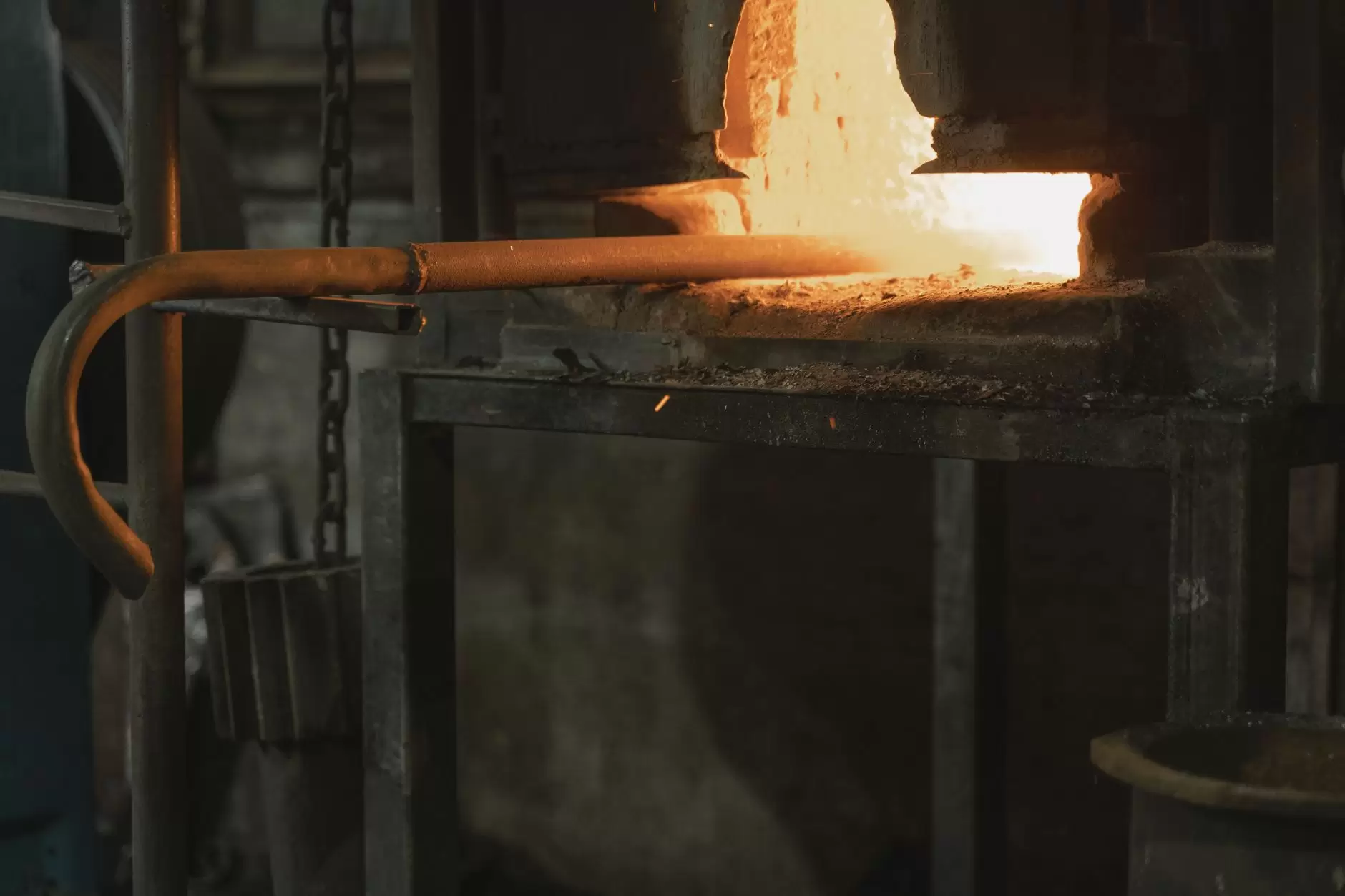
The second datum is batch-versus-continuous duty. A continuous kiln or melter can present a flat draw for as long as the process runs. A batch oven or induction furnace cycles with the charge: demand rises as heating begins, holds through the soak, and drops between batches. The grid planner sees the second as a block that starts and stops on a production schedule, not a steady load. The same total energy produces a very different capacity requirement.
The conversion equipment then shapes the electrical profile. A heat pump brings a compressor, so its draw includes motor inrush and may ramp with controls. An electrode boiler can be designed to modulate, but direct resistance heating often steps between heating elements. The electrical profile also depends on how the heating elements are arranged: a three-phase electrode boiler may modulate continuously, while a bank of resistance elements may switch in stages. The difference shows up in voltage flicker and in how smoothly the site can follow a signal.
A thermal store changes which of those shapes the network sees. The IEA describes thermal storage as the enabling technology that can connect low-cost variable renewable electricity supply with continuous industrial heat demand. If the store is sized to the process, the electric heater can draw during hours of cheap or abundant electricity while the process continues to receive heat from the store. The electrical draw then moves away from the process duty, although the energy required does not shrink.
That store can be unusually simple. The IEA describes thermal storage systems built from sand, cement and bricks storing heat up to 1,000°C at around USD 15-20 per kWh, cheaper than chemical batteries and not reliant on critical mineral supply chains. For the grid, the relevant feature is not the material but the decoupling it creates: the electric heater can run as a controllable block while the process continues on stored heat. That turns a once-continuous thermal load into a discretionary electrical load, within the limits of the store’s capacity and the plant’s production schedule.
The flexibility has to be designed into the process. A facility with no thermal store and a fixed production schedule offers the system operator little beyond the option of shutting down, which is costly and rarely procured as a grid service. The distinction that matters is between a load able to move its electrical draw across the day and one that can only switch on or off. A switching load still alters the demand curve, but in steps set by the process rather than by system conditions, and electrifying it moves the fuel from gas to electricity without giving the operator much to schedule around. Where a controllable load or storage can act as a grid asset, the same energy becomes a planning option rather than a fixed block.
Transmission-Connected and Distribution-Feeder Sites Present Different Problems
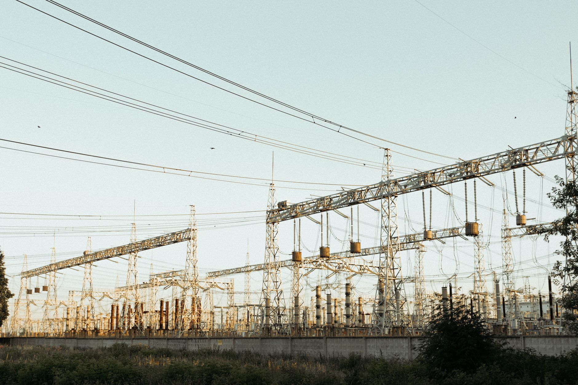
A large continuous process at a transmission-connected plant can look like a block of new baseload from the system operator’s perspective. The question is whether the local substation and the wider network can carry that block through the hours the process runs. The operator sees an aggregated demand, not the individual equipment. A single large electric furnace can present a flat, high-magnitude draw for the duration of a production campaign.
The same thermal requirement on a distribution feeder has different consequences. A mid-size food processor adding an electric boiler or heat pump competes for capacity with other feeder loads, and the starting current and cycling pattern matter as much as the average draw. The distribution utility sees individual equipment starting and stopping, not a smooth block. These are different planning problems: a transmission boundary is about sustained transfer, while a feeder is often about local voltage and protection margins.
Keeping the two levels separate matters because the same load can be unremarkable at one point in the network and binding at another. The system operator’s demand data for a given market is the only basis for claiming what a particular feeder or substation can host. Without that data, the load shape should be written as a design possibility — a continuous process can present a flat draw — rather than as a property of industrial load in general.
A transmission-connected site can also interact with system-level constraints differently from a feeder-connected site. Large industrial loads sometimes have the option of interruptible or demand-response arrangements, where the site reduces draw in exchange for a tariff or a payment. A distribution feeder, by contrast, may rely on local voltage regulation rather than a market signal. The two are not interchangeable, and a rule that applies in one market or at one network level cannot simply be carried across to another.
A Building Heat Pump Is the Wrong Comparison
Industrial process heat follows production, not outdoor temperature. A building heat pump peak arrives with cold weather and can be seasonal, but an industrial dryer or furnace runs when the plant runs. That distinction is why the process electrification load cannot be inferred from the residential or commercial heat-pump profile. The closest analogue in electrified transport is fast charging, where a brief high-power draw matters more than the energy over a day.
The International Energy Agency estimates that substituting natural gas and other fossil fuels with electricity for EU industrial heat at scale would imply around 600 TWh per year of additional electricity demand, comparable to the combined annual electricity consumption of Germany and the Netherlands. That is an energy total, not a peak-coincident capacity figure. The planner’s question is how much of that total lands during system peak, because the same energy spread evenly across a day is a very different asset than the same energy concentrated in a morning production ramp.
What Remains Unresolved for the Planner
The IEA has also identified the barriers that keep this load from scaling quickly: unfavourable electricity-to-gas price ratios, long grid connection lead times and the absence of clear policy frameworks. Each barrier affects the shape a planner will actually see. A plant that cannot get a long lead-time transmission connection may first electrify a single batch process on the existing feeder; a plant facing poor price ratios may switch only when an industrial tariff or storage arrangement makes the load worthwhile.
What is still unresolved for the planner is the coincidence of the electrified process with system peak, and the control or thermal storage that decides it. A continuous process can be a flat block, but only if it runs through peak; a batch process can be flexible, but only if someone is paid or instructed to cycle it. Where thermal storage is installed at the process or upstream in the feeder is an open design choice, and it is that choice, together with the process schedule, that decides the load the network sees.
References
- IEA — Renewables for Industry, Executive summary, https://www.iea.org/reports/renewables-for-industry/executive-summary
- IEA — Renewables for Industry, https://www.iea.org/reports/renewables-for-industry