When a data center rack moves from conventional servers to densely packed AI accelerators, the changes in AI server rack power and cooling appear most visibly in the electrical distribution and thermal systems. Those two systems are not independent. A decision in one forces a matching decision in the other, and until both are designed together, the rack cannot operate at its intended capacity. For many operators, this is where the practical difficulty of high-density AI begins.
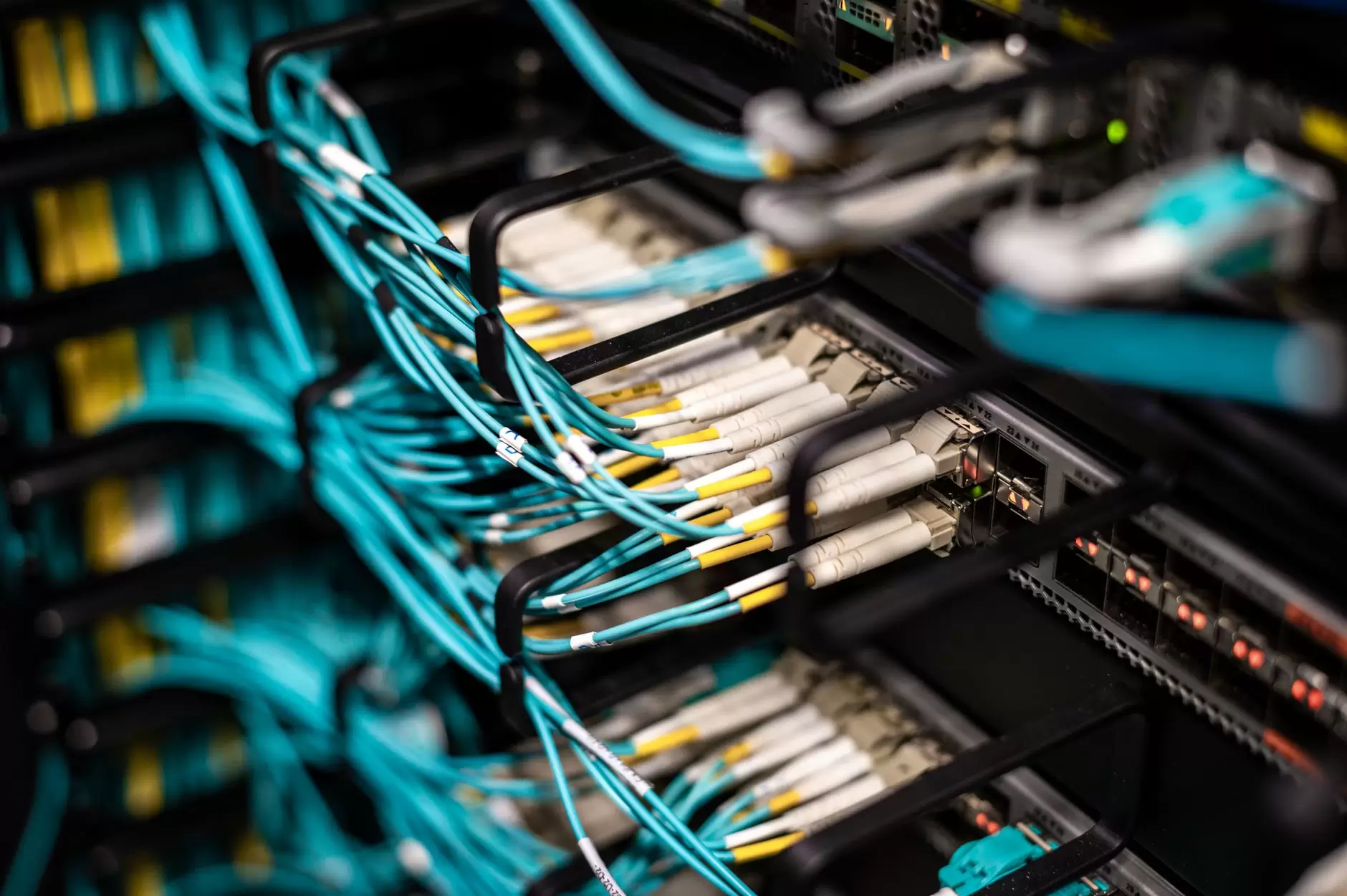
High-density racks concentrate dozens of accelerator cards, networking switches, and power conversion stages in a compact enclosure. Nearly all of the electrical energy delivered to that enclosure leaves it as heat. The engineering task is therefore to deliver power safely and remove heat inside the same physical footprint, without allowing either function to constrain the other. This rack-level concentration is a key driver of the data center electricity demand trend now visible across the sector.
Why Rack Power Density Changes the Design Problem
Conventional enterprise racks draw relatively modest power, and their power and cooling infrastructure can be selected independently. AI racks draw considerably more, and that difference changes how current enters the rack, how much each connector must carry, and how much heat must be rejected from a single enclosure. The combined load pushes standard power distribution units toward their practical limits.
Rack-level engineering is no longer a commodity decision. Power distribution, connector selection, and cooling approach interact in ways that a design selected for a conventional rack may not tolerate. The required changes are not simply a matter of adding capacity; a higher-power rack can require a different electrical architecture, a different thermal architecture, and a different maintenance model. This interaction is what makes high-density AI racks a distinct engineering problem rather than an extension of traditional server design.
IEA data centre tracking identifies rising energy intensity in high-performance equipment as an underlying trend. That energy intensity is not evenly distributed; it concentrates in the racks where accelerator density is highest, which is where the electrical and thermal constraints first appear. This concentration is why rack-level design choices now receive the attention once reserved for facility-level systems.
The Limit of Air Cooling
Air has a finite capacity to carry heat. Removing the heat produced by a high-density rack with air alone requires high airflow rates. High-airflow fans move large volumes of air, consuming energy and producing noise. As airflow increases, the air leaving the rack approaches the inlet temperature, so further increases yield diminishing returns while fan power and noise continue to climb. At some point, air cooling stops being practical even if more fans could physically be fitted.
That practical limit has pushed the industry toward liquid cooling. Direct-to-chip cold plates remove heat at the processor die rather than relying on air to carry it away. Liquid can transport far more heat per unit volume than air, making it practical to remove much higher heat loads within the same rack footprint, so the same rack can reject more heat with much less airflow. The trade-off is added plumbing, leak containment, coolant chemistry, and maintenance complexity.
But liquid cooling is also an electrical decision. Routing conductive coolant near high-power electronics requires new grounding and isolation designs. Leak detection becomes an operational necessity rather than an optional add-on. ASHRAE TC 9.9’s Liquid Cooling Guidelines for Datacom Equipment describe the measures needed when conductive coolants are routed through high-power racks. The allowable temperature envelope for IT equipment, as defined in ASHRAE TC 9.9’s Thermal Guidelines for Data Processing Environments, narrows the design space as rack heat density rises.
Even in liquid-cooled racks, not all components can be cooled by direct contact. Memory modules, voltage regulators, and network interfaces still release heat that air must carry away. Liquid cooling therefore changes the split of heat rejection. It rarely eliminates air handling entirely. Most direct-to-chip deployments retain some airflow, which means the facility must manage both air and liquid loops rather than trading one for the other.
The Liquid Cooling Chain Is Longer Than It Looks
Liquid cooling is sometimes discussed as though the coolant absorbs heat and the problem is solved. In practice, the rack-level cold plate is only the first stage. Heat travels from the processor die into the cold plate, then into a rack coolant loop that circulates through a manifold to collect heat from multiple servers. From there, the loop meets a coolant distribution unit, or CDU, which transfers heat to a separate facility water loop. That facility loop then carries the heat to chillers, cooling towers, or dry coolers that reject it outside the building.
This chain matters because liquid cooling is not self-contained. The CDU is the boundary between the internal coolant loop and the facility water system. It controls pressure, flow rate, and temperature, and it often includes filters and sensors to prevent contamination between the loops. If the facility water loop cannot reject the heat because the chillers are undersized, the water temperature is too high, or the outdoor heat rejection equipment is constrained, then the rack-level cold plates cannot function at full capacity.
The CDU also provides a physical separation that is easy to overlook. In many designs, an isolation heat exchanger inside the CDU keeps the rack-side coolant from mixing with the facility water loop. That separation is what allows the rack loop to use a different fluid — treated water, propylene glycol, or a dielectric fluid — while the building loop uses treated water managed for corrosion, biological growth, and freeze protection. The CDU must reconcile these two fluid systems without allowing them to mix.
Electrical Delivery Inside the Rack
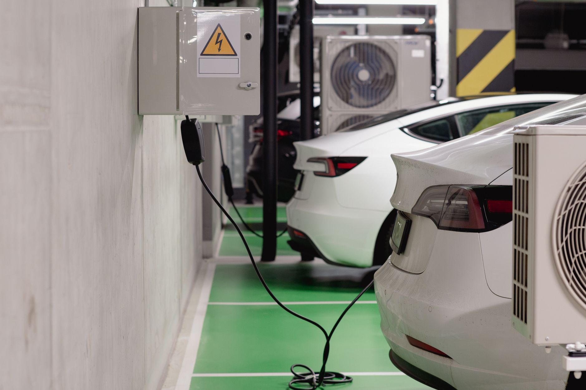
Higher rack power changes how electricity is distributed within the enclosure. Conventional rack power distribution units with standard outlets are often insufficient for dense AI configurations. Operators are moving toward busbar systems that deliver higher current safely and use higher distribution voltages to reduce current and therefore resistive losses. Higher-voltage distribution also reduces conductor size, freeing space for cooling hardware.
At these power levels, overcurrent protection coordination becomes essential. A fault in one server or power branch should ideally be isolated without unnecessarily taking down the rest of the rack, but the protection scheme must clear the fault quickly enough to prevent damage. This requires careful selection of circuit breakers and fuses, plus intelligent power monitoring that can detect abnormal current draw before it becomes a hazard. Vendor-neutral rack specifications such as the Open Compute Project’s Open Rack v3 provide a reference for busbar-based power delivery in high-density equipment.
Electrical design also interacts with the cooling approach. Liquid-cooled racks may not require the same airflow, allowing denser component placement, but they still need power distribution that can handle the concentrated load without overheating cables or connectors. A busbar that performs acceptably in a traditional air-cooled rack can become a constraint when surrounded by hot components and reduced airflow.
Operational and Commercial Consequences
Maintaining a high-density AI rack is different from maintaining a traditional server rack. Liquid cooling loops may need to be drained and refilled during component replacement, increasing the time and skill required for routine service. Leak detection systems add sensors and monitoring points that must themselves be maintained. The coolant must be monitored for chemical stability and microbial growth, which can degrade thermal performance and corrode components.
The higher power and heat density also affect reliability. A cooling pump failure or a leak in one cold plate can cause rapid temperature rise across multiple accelerators, potentially triggering thermal shutdown or hardware damage. That concentration of risk makes redundancy and failover more necessary and more expensive at the rack level. Spare parts strategies shift as well: a damaged cold plate or failed CDU is not a commodity item that can be swapped from a shelf in minutes.
These constraints reach beyond the data center operations team. Building-level electrical demand changes because liquid cooling still requires pumps, CDUs, and heat rejection equipment, so the choice between air and liquid cooling affects the total power drawn by the facility, a point covered in the broader analysis of why data center electricity demand is surging. Developers face a different capital question: whether to build shell space for air-cooled racks or invest early in piping, leak containment, and facility water loops that can support direct-to-chip cooling. Equipment vendors are pushed to certify connectors, cold plates, and power distribution for sustained contact with coolant, expanding testing and warranty obligations.
Where Rack-Level Design Is Heading
The industry is moving toward more integrated rack designs in which power, cooling, and monitoring are treated as one system rather than separate subsystems. Higher-voltage distribution, direct liquid cooling, and embedded sensors are becoming more common in AI deployments, though adoption varies with facility type and operator. At the same time, some operators are testing immersion cooling, where entire servers are submerged in dielectric fluid and air cooling is eliminated at the rack level.
Each approach involves trade-offs. Direct-to-chip cooling is efficient but requires precision manufacturing and maintenance, and it still depends on facility-level water or chilled-water systems to reject heat. Immersion cooling simplifies some thermal challenges but introduces fluid management and material compatibility issues, along with questions about serviceability and component warranties. The choice depends on workload characteristics, existing building infrastructure, and operational tolerance for complexity.
Further increases in compute density continue as accelerator performance and interconnect technology advance. The industry still needs common standards for leak detection, coolant compatibility, and service procedures across vendor ecosystems. Until those standards settle, operators carry much of the engineering burden themselves. How those rack-level constraints play out varies with facility design, climate, and site infrastructure, but they nonetheless shape deployment outcomes in AI data center buildouts around the world.
References
- ASHRAE TC 9.9 — Thermal Guidelines for Data Processing Environments — temperature and humidity envelopes for IT equipment and the limits that push high-density racks toward liquid cooling.
- ASHRAE TC 9.9 — Liquid Cooling Guidelines for Datacom Equipment — CDU isolation, leak detection, grounding, and dual-loop operation requirements for liquid-cooled IT equipment.
- IEA — Data Centres and Data Transmission Networks — context on rising energy intensity in high-performance data centre equipment.
- Open Compute Project — Open Rack v3 Specification — reference design for busbar-based power distribution in high-density racks.